HCT INSTRUMENTS | HESP - Cassegrain unit
Instrument
HESP main page |Cassegrain unit |Spectrograph |Calibration unit |Observing modes & Efficiencies
Cassegrain unit
ADC corrector|Auto guiding unit|Fiber input and Alignment cube
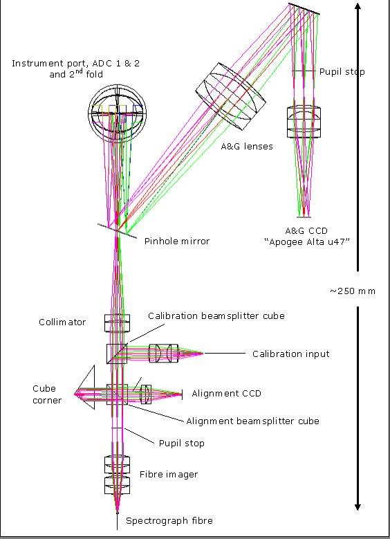
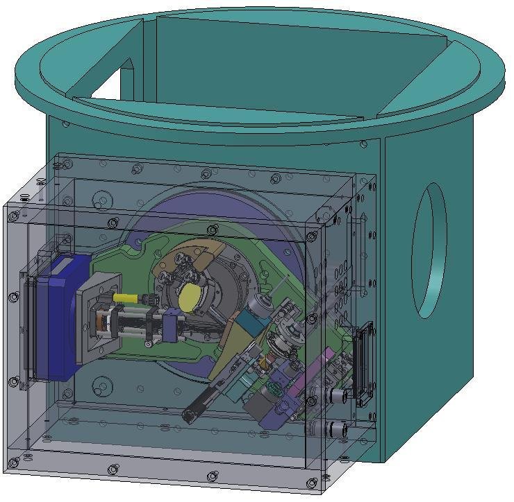
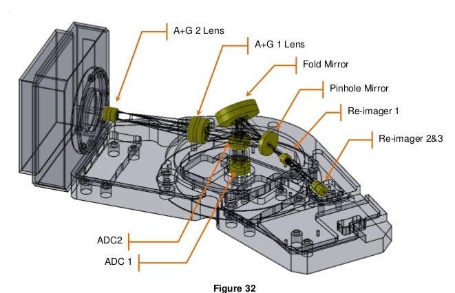
Light from HCT (2m telescope) at f/9.2 is directed by a 45° fold mirror through a side port of the instrument mounting cube. A 45° fold mirror redirects the light parallel to the instrument mounting plane. The cassegrain unit includes the ADC corrector, Auto guiding unit along with fiber input unit and an alignment cube.
ADC corrector
Auto guiding unit|Fiber input and Alignment cube
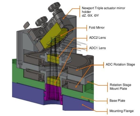
The Atmospheric Dispersion Corrector (ADC) consists of two counter-rotating “Direct-Vision Doublet Prisms” (DVDPs). It is placed between the instrument port and the second fold mirror in front of the telescope focus.
Auto guiding unit
ADC corrector|Fiber input and Alignment cube
A large symmetrical triplet lens collimates the 100 arcsecond telescope guiding field onto an Apogee Alta u47 broadband CCD which is a 1024 x 1024 array of 13 m square pixels (5pixels/arcsec)
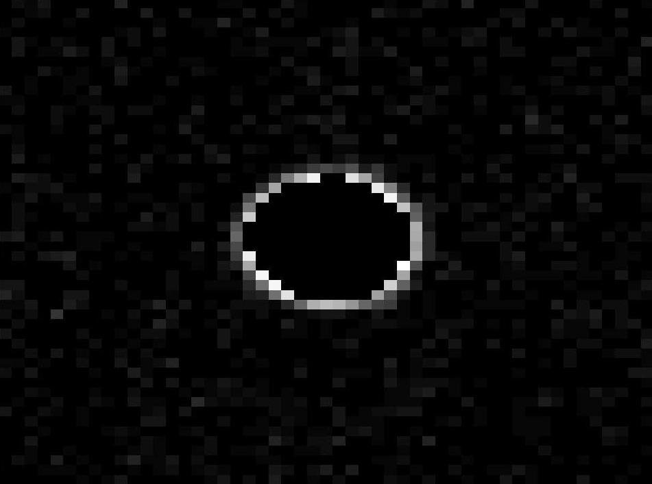
The reflected light of the pinhole plate will be used for guiding. Some cases we will be able to get a guide star within 100arcsec field.
Fibre input and alignment cube
ADC corrector|Auto guiding unit
A symmetrical triplet lens collimates the light from calibration fibres which are fed by a lamp assembly in the spectrograph room. A deployable beamsplitter cube (95/5) can direct about 5% of the calibration light into the fibre imager and the sky spectrograph fibre. About 95% of the object light is passed undisturbed so that a calibration spectrum can be acquired simultaneously with an object spectrum. When the deployable beamsplitter is replaced with a plane mirror both fibres can be calibrated simultaneously.
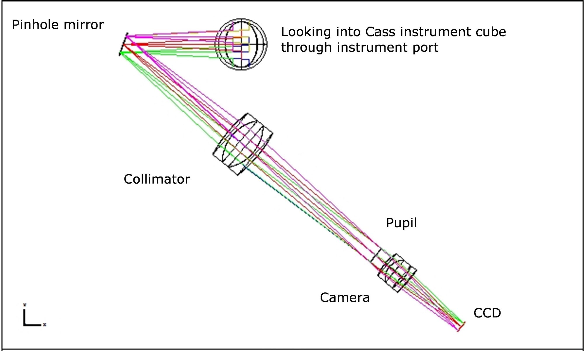
A deployable alignment beamsplitter cube is inserted in the collimated space between the calibration beamsplitter mirror and the pupil stop. The function of the beamsplitter is three-fold:
- It directs the light from the back illuminated spectrograph fibres into a small general purpose CCD camera;
- It directs light from the pinholes into the CCD camera; and
- It can direct light from the calibration fibres into the CCD camera.
In this way, the images of the pinholes, the spectrograph fibres and the calibration fibres can be co-aligned for optimum throughput by overlaying their images on the alignment CCD.