Visible wavelength broad band imager
The broad band imager is used to observe the solar photosphere and low chromosphere. The wavelenths will be chosen such that the observation can be carried out from photosphere to the chromosphere. A list of possible filters along with the observation level in the solar atmosphere and their scientific purpose is presented in Table 1.
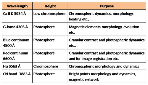
Ca II K 3934 filter of about 2-3Å band pass will be used to observe the low chromosphere. The large band pass will allow higher amount of flux that can be useful to study the oscillations. Since the cadence will be very high one can use the speckle reconstruction technique to get high contrast images.
G-band images are obtained in the band of CH molecule. The images have very good contrast for the magnetic features. The pass band of the filter is about 10Å. Blue and red continuum filters will have a band pass of 5\AA. The images taken from these filters will have a better contrast to the granulation than the G-band images. These images can be used to align the different types of images obtained from various telescopes across the world. These images are also useful to find the horizontal velocity in the granulation and pores.
The Hα filter will have a band pass of about 0.25Å. The Hα images have very good contrast for the higher chromosphere. This is the only line that shows the fibril nature of the chromosphere and hence also shows the direction of the magnetic fields, chirality etc.
CN molecular band images are similar to the G-band images and have very good contrast for the magnetic elements. The band width of the filter is about 5-10Å. Further, there will be some options to include filters like TiO (7058\AA), Ca II 8542 Å, Na I 5896 etc. to observe the sunspot umbra, upper chromosphere and lower chromosphere.
Fabry-Perot based narrow band imager
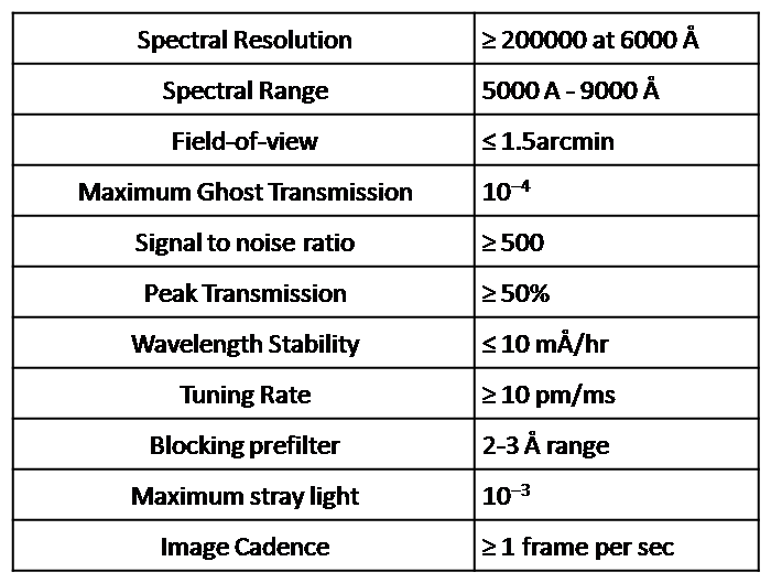
Over a decade, Fabry-Perot (FP) based narrow band filters have been used extensively to image the solar atmosphere at various heights. The FP based filters have notable advantage of fast tunability and high light throughput compared to the Michelson interferometer and birefringent filters. However, those designs have a limitation on spectral resolution. Two or three FT etalons in seriers has better performance than just a single FP in respect of 1) high spectral resolution, 2) large spectral range, 3) large field-of-view, 4) high light throughput to have sufficient light, 5) fast change between wavelenghts 6) minimum stray light. Table 2 gives the design specifications of the FP based imaging spectrometer to meet our scientific goals
Spectro-polarimeter
The spectro-polarimeter (SP) design for the NLST will be based on the Spectropolarimetry for the Infra-red and Optical Region (SPINOR) design. It would consist of two units:
- Polarimetric Modulation unit
- Flexible Spectrograph unit
Polarimetric Modulation Unit: The polarimetric modulation unit will be placed close to the secondary focus (F2) of the NLST (see the optical layout of the NLST for the location of F2). The modulator will consist of an achromatic 0.375 waves rotating waveplate. The achromatic retarder can either be made using the Pancharatnam technique or using the bi-crystalline achromatic retarder (Guimond and Elmore, 2004). Both the achromatic retardershave been in operation for several years in Astronomical observations. The bi-crystalline modulator used in the SPINOR covers a wide wavelength range from 430nm to 1600nm. The details of the SPINOR instrument can be seen in Socas-Navarro et al. (2006). The modulator optics will be Anti-reflection (AR) coated in order to reduce any reflection loss. The wavelength range covered by this modulator can accommodate most of the spectral lines of interest to the scientific community.
Just before the modulator optics, a calibration unit will be placed. The calibration unit is a must in order to calibrate any residual polarization from the telescope. Due to this calibration mechanism, the achieved accuracies can be as high as 10^{-4}. The calibration unit will consist of an achromatic quarter-wave plate followed by an achromatic linear polarizer. When the quarter wave plate and the polarizer are in the optical beam, then it produces circularly polarized beam to the modulator. For the generation of linear polarization, the quarter wave plate is taken out of the beam. During the regular observations of the solar features, both the quarter wave plate and the polarizer will be out of the beam. The rotation modulator uses the principle similar to that of the Advanced Stokes Polarimeter (Elmore et al., 1992).
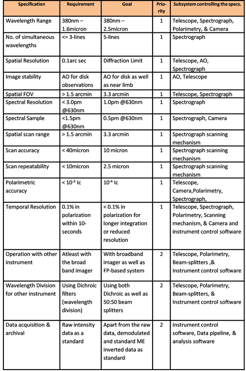
Flexible Spectrograph unit: A spectrograph at the focal plane of the telescope is used to capture the spectral line profiles. A 40-60micron slit at the focal plane will be the slit of the spectrograph. The required instrument specifications are listed in adjoining Table.
Read more about the instrument Spectropolarimetry
Adaptive Optics system
In most cases, the performance of an optical telescope is limited not by the telescope's optical properties but by the turbulence in the atmosphere above. The temperature fluctuations in the atmosphere lead to fluctuations of the index of refraction which by themselves lead to degradation of the image quality.
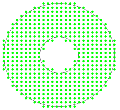
There basic parameters, Strehl ratio, Freid's parameter r0, and atmospheric time constant \tau decides the quality of telescope images. Desinging an AO system requires a detailed knowledge of these parameters. The number of subapertures determines the number of degrees of freedom and therefore the maximum correction which can be achived. Since the solar granulation is the structure (2arcsec spacial size) the AO has to lock on, the subaperture diameter has to be at least 63mm. Based on site characterisation results, the proposed AO system for NLST is shown in Figure 1. The actuator spacing in x direction is 7.8mm and the spacing in y direction is 7.2 mm. 25 subapertures across the telescope (i.e., 26 actuators across the telescope) corresponds to a subaperture diameter of 80mm.