Telescope Structure
Based on the present optical diagram, the concept for telescope structure has been worked out that will be further modified/ changed based on the inputs and review from various teams.The telescope structure consist of following sub structure:
- Elevation Structure
- Azimuth Structure
- Interface between the building and the azimuth structure
- Elevation and azimuth rotating mechanism
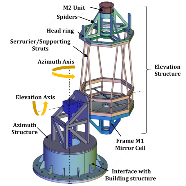
Elevation Structure
This is one of the main systems in the whole of NLST. The mechanical structure is mainly made out of long struts and frame work. This is necessary since the whole primary and secondary mirror should be well exposed to natural atmospheric wind flow during science observations. This ensures that the cold wind blowing over the optical elements prevent the mirror from excessive heating due to absorption of solar energy in visible and IR wavelengths.
Azimuth structure
This is a structure which is connected to the main elevation structure of the telescope on one side and at a right angular plane parallel to the ground, it interfaces with the azimuth axis bearing system of the telescope. The elevation axis is driven by a set of drive system having motor, gear reduction unit, bearing with housing etc. The azimuth axis is driven by another set of drive system which is integrated to the perpendicular plane which is parallel to the ground.
Azimuth structure-Building Interface
This is a unit which provides connectivity between the azimuth structure and the building top at the observation floor. It ensures that the height of telescope elevation axis from ground is maintained to the required level. It also houses many parts of the azimuth drive system.
Elevation and azimuth rotating mechanisms
Elevation drive system: The telescope need to be driven about the elevation axis to get the required altitude pointing. It is proposed to be driven by a servo controlled motor and the bearings are proposed to be cross roller bearings. These bearings provide very high load carrying capacity, can be tuned to have zero backlash including low co-efficient of friction. Additionally these bearings will have gear teeth as part of inner or outer race which can be driven by the gear reduction unit integral with drive motor.
Azimuth drive system: The proposal for azimuth drive system is to use a fairly new type of bearing system (may be about 15 year old), known as R-Guide bearings. Many telescopes earlier were using hydrostatic bearings in order to get high stiffness with minimum bearing running noise (electrical as well as mechanical) transmission to the science data capture. With the advent of new mechanical technologies as well as advanced electrical noise filtering,now it is possible to achieve the same level , (or even better sometimes) of noise free bearing systems. Here, the bearing is similar to linear guide bearings, with the difference that linear is converted into a smooth curved radius during design and manufacturing.
Instrument Rotating Table (IRT)
The purpose of providing Instrument Rotating Table (IRT) is to counter-rotate the table to compensate for the focal plane image rotation caused by the alt-azimuth telescope mount movement. This IRT table will have servo controlled optical benches fixed on to its floor. Optical instruments are assembled on these optical benches which are aligned with respect to the focused beam coming after mirror M7.
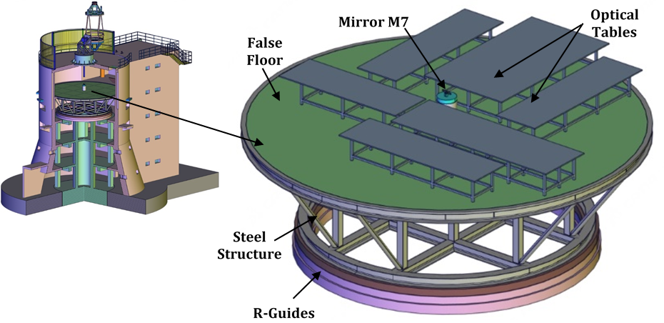
- IRT system will have stiff structure to support instruments tables and a false floor with suitable vibration isolation for personnel working around the instruments.
- Base structure of IRT is constructed from large structural members (wide flange and box beams).
- The instruments loads are carried on re-locatable instrument support beam underneath the false floor.
- The bearing system proposed for IRT rotation is R-Guide type.
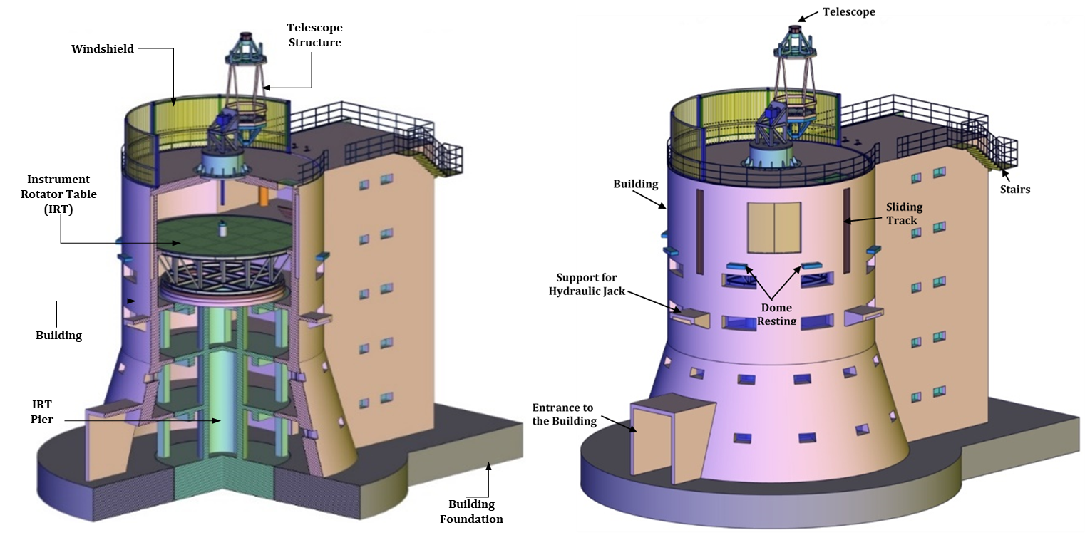
Telescope Building
The conceptual Telescope Building includes:
- Interface for supporting the telescope system.
- Interface for the dome support and guide ways for sliding down the dome.
- Pier for 10m dia Instrument Rotator Table (IRT) that is isolated from other parts of the Building.
- The lift having vibration isolation from the building to avoid vibration transfer to the telescope and its instruments during operation. This lift and stair case shall provide access to all the floors from Ground Floor to top floor (Observation floor).
- Rooms for laboratories, storage, workshop, Control System etc.
- The observation floor which will have a Jib crane system for lifting and moving the telescope structure as well as any other equipments like M1 Mirror Handling & removal fixture between observation floor and the ground floor.
- EOT crane in ground floor for loading/unloading of equipments.
- A sliding and swinging crane to handle and move the optical table and other heavy accessories, in and out of IRT table
Handling Equipment
NLST system needs many handling equipments which are to be permanently fixed in the building or to be kept ready and can be moved on wheels whenever required. Preliminary designs for some of the following major handling systems are completed.
- Primary mirror M1 handling system
- 10 ton capacity Jib crane to be fixed on the building top
- Monorail crane with provision to swing inside the building to handle equipments on IRT
- Material handling EOT crane at ground floor
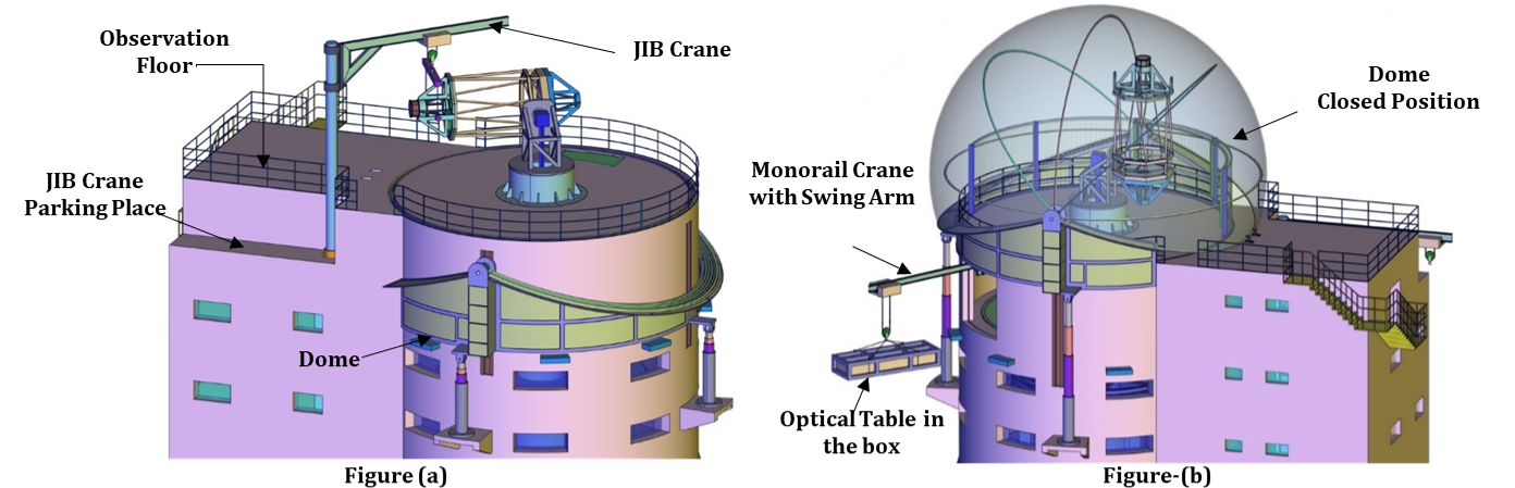
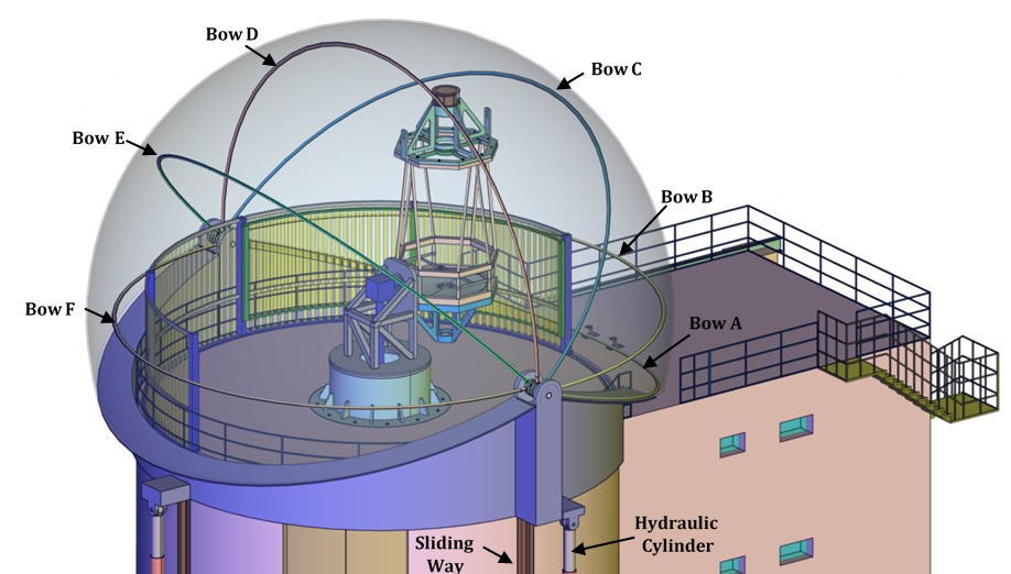
Dome
Dome is required to protect the telescope system when there are no science observations and when the dust storm or high velocity wind blows over the region. The different four retractable dome concept have been worked out inhouse and one of them is shown in the below figure.