The Gauribidanur Observatory
- Radio astronomy at the IIA |
- Gauribidanur Telescope |
- Gauribidanur Radio heliograph |
- Gauribidanur Low-frequency Solar Spectrograph |
- Gauribidanur Radio Interferometric Polarimeter |
- Mauritius Radio Telescope |
- Brazilian Decimetre Array |
- Public Outreach Programme
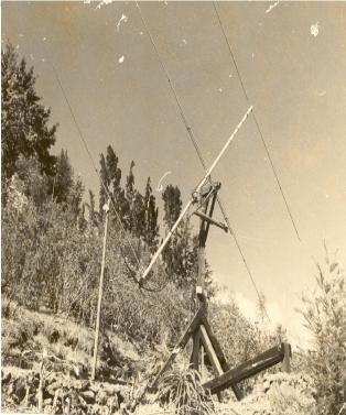
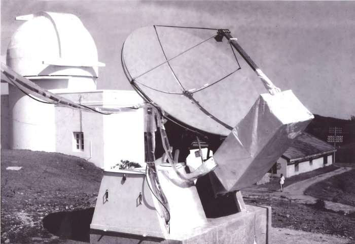
The main focus of the radio astronomy facilities at IIA is on the observations of the Sun. The early observations date back to the 1950s at the Kodaikanal observatory of the institute. Continuous recording of the solar radio noise flux commenced in 1952 using a 100 MHz interferometer with Yagi antennas. A 20 feet paraboloid for observations at frequencies in the decimetre and metre wavelength range was set up on an equatorial mount in 1961. Work on an interferometric aerial for scintillation studies at 60 MHz was also started during this period. Under the Kodaikanal - Yale Project, recording of radio radiation from Jupiter at a frequency of 22.2 MHz was started using a phase switching interferometer. The custom-built 3 GHz wavelength radio receiver from the Commonwealth Scientific and Industrial Research Organization (CSIRO), Australia was put to use in 1965. Mounted on a 2 m paraboloid, it was used for regular solar patrol. In the early 1970s, small-sized antenna arrays operating at 25 MHz were used to obtain information on the radio bursts from the outer solar corona with high temporal and spectral resolution.
|
The Yagi antenna system |
The 20 feet dish 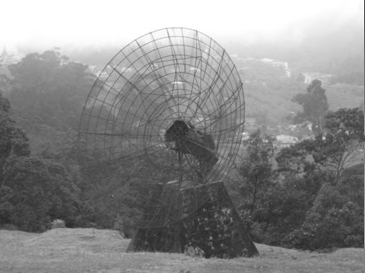
|
The 3 GHz antenna system (front) and the Kodaikanal Tunnel Telescope (rear)
|
|
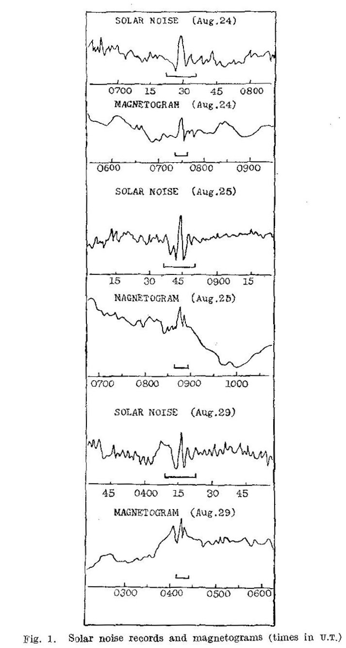
The earliest solar radio observations in the country - at 100 MHz from the Kodaikanal observatory in 1953
A.K.Das and B.N. Bhargava. Nature, 1953 Vol.172, p855 |
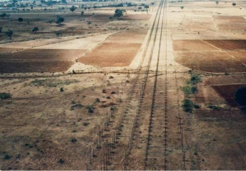
Since 1976, the Institute operates a decametre wave radio telescope jointly with the Raman Research Institute at Gauribidanur (Latitude:13.60° N; Longitude:77.44° E), about 100 km north of Bangalore. The GEETEE consists of 1000 dipoles arranged in a 'T' configuration, with a 1.4 km East-West arm and a 0.5 km South arm. It has been engaged in the study of radio waves at 34.5 MHz emanating from the Sun and various other diverse objects in the sky. The most notable observations with the array till date are: (i) first two-dimensional images of the radio emission associated with slowly varying discrete sources in the outer solar corona, (ii) all-sky survey of radio sources at 34.5 MHz in the declination range ~-30° S to 60° N, and (iii) low frequency carbon recombination lines in the astrophysical sources. Observations of gaseous remnants of exploding stars and the apparently vacant space between members of a cluster of galaxies have also been obtained. The main studies at present pertain to pulsars with a new and sensitive backend receiver. A small broadband array in the frequency range 35 - 70 MHz was also operated during mid 1980s at this Observatory.
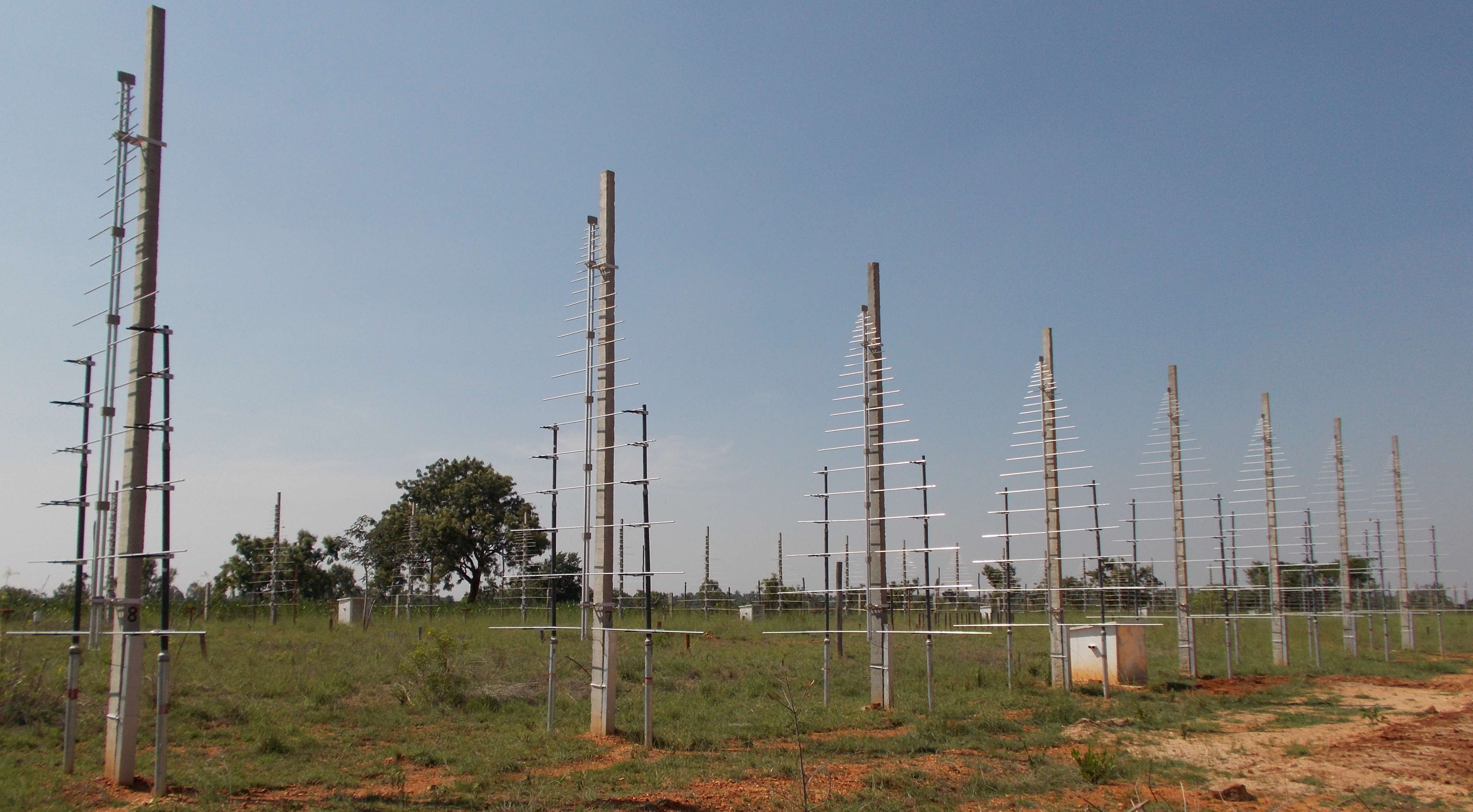
A radioheliograph to obtain two dimensional images of the solar corona simultaneously at different frequencies in the range 40 - 150 MHz is also functional here since 1997. The basic receiving element used is a log-periodic dipole (LPD), and the array consists 384 of them configured as 64 groups. The dipoles are arranged in a 'T' configuration similar to the GEETEE. The present spatial and temporal resolution of the GRAPH are ~3 arc min (@ 150 MHz) and ~256 msec, respectively. The array is in regular operation and the observing period is ~9 AM - 5 PM (03:30 - 11:30 UT), everyday. A 4096 channel digital correlator is used as the back end receiver to extract the strength and positional information of the radio emission from the solar corona and the various discrete structures there. The frequency coverage of GRAPH is unique that it provides useful information on the solar corona in the height range ~0.2 - 0.8 Rs above the solar surface (Rs = radius of the Sun = 696000 km), which at present is difficult to observe at other frequencies in the electromagnetic spectrum. No other radio telescopes, dedicated for solar observations, are presently operational in the above frequency range anywhere in the world. Some of the notable observations with GRAPH till date are: (i) density / temperature diagnostics of pre-event structure of a CME, (ii) velocity / acceleration of a CME close to the solar surface, (iii) 'true' speed of a CME in the three-dimensional space, (iv) estimation of the parameters of a CME at ~40 Rs from the Sun through angular broadening observations of a distant cosmic radio source, (v) seismology of the solar corona using radio burst emission as tracers, (vi) coronal electron density gradient in the height range ~0.2 - 0.8 Rs above the solar surface, and (vii) plasma characteristics of the radio emission associated with emerging magnetic flux from the sub-surface layers of the solar photosphere.
A high resolution radio spectrograph is used in conjunction with the GRAPH for obtaining dynamic spectrum of the transient emission from the solar corona. The antenna system consists of 8 log periodic dipoles. Presently spectral information is obtained with an instantaneous bandwidth of ~250 KHz, and a temporal resolution is ~43 msec. The GLOSS and the GRAPH together provide spectral and positional information on eruptive solar activity, again an unique combination. The observations so far have provided clues to: (i) electron acceleration associated with small scale non-thermal energy releases in the solar atmosphere, (ii) occurrence of radio bursts associated with successive magneto hydrodynamic shocks in the solar corona, and (iii) source region of a CME through observations of transient 'absorption' bursts.
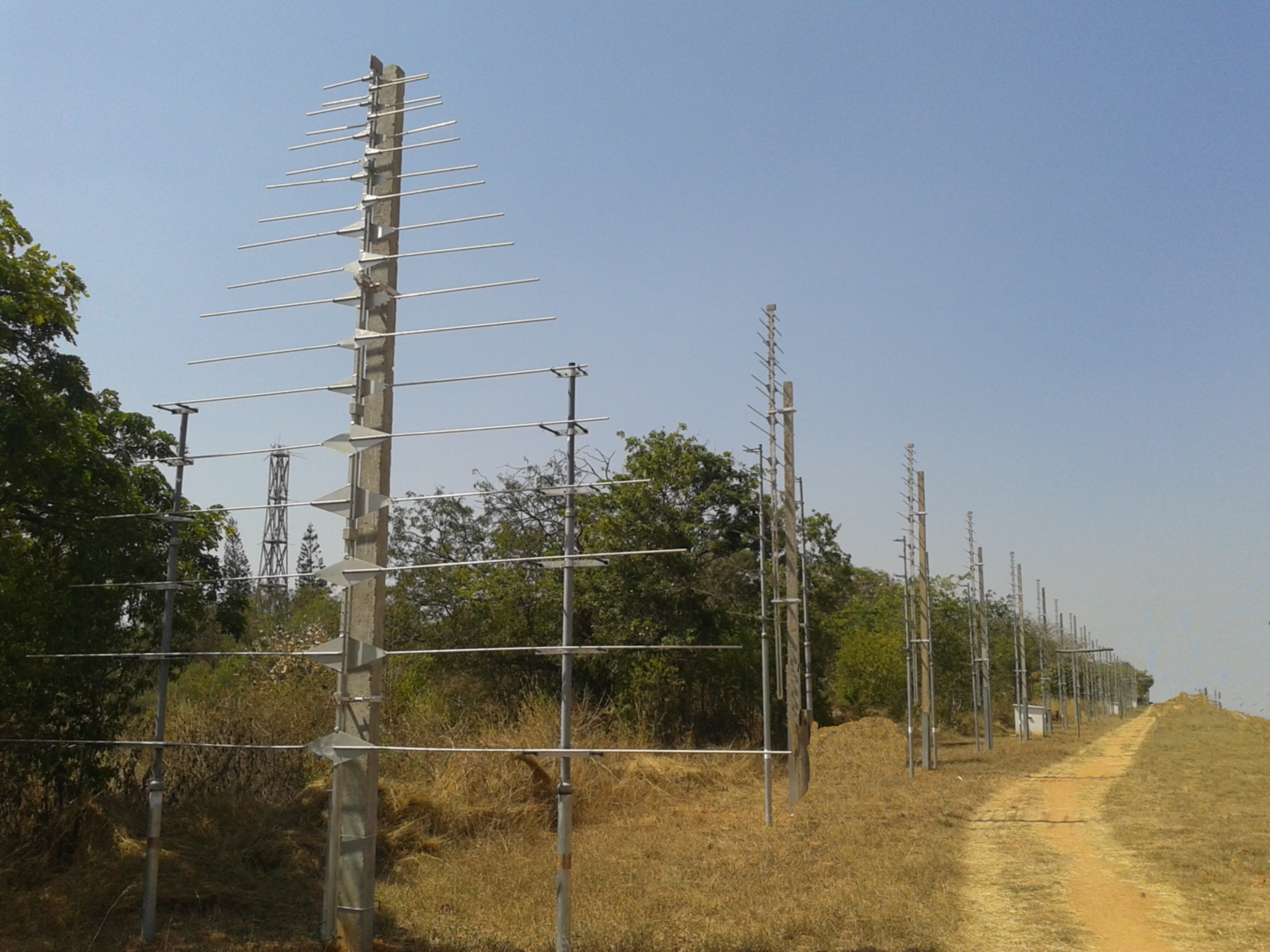
Based on the theoretical formulations for the response of a correlation interferometer to polarized radiation, an east-west one-dimensional array of 40 log periodic dipoles have been set up to probe the coronal magnetic field in the height range ~0.2 - 0.8 Rs, above the solar surface. The dipoles are arranged as 3 groups oriented at 0° & 90° with respect to the terrestrial north. This helps in capturing the polarization state of the incident radiation with good accuracy. The idea is to get information on the coronal magnetic field through observations of circularly polarized radio emission from the discrete sources in the corona. The spectral dependence of the observed emission in the above height range is derived through simultaneous multi-frequency observations.
In addition to the above antenna arrays, a large synthesis telescope operating at 151.5 MHz was constructed in the early 1990s on the island of Mauritius (Latitude:20.14° S; Longitude:57.74° E) in collaboration with the University of Mauritius and the Raman Research Institute. The MRT is a 'T' shaped antenna array and simulates a dish antenna of ~2 km diameter. The primary goal was to make a radio map of the southern sky in the declination range ~-10° to -70° and generate a point source catalogue at 151.5 MHz. This will compliment the existing Cambridge 6C catalogue on radio sources in the northern hemisphere. An added advantage of the location is that a better study of the center of our Galaxy is possible since the latter lies almost overhead there. Observations of the Sun at 151.5 MHz with an angular resolution of ~2 arc min were also carried out with MRT. Scientists of IIA used the MRT & GRAPH jointly to investigate the plasma parameters associated with the electron acceleration in the aftermath of eruptive activity in the solar atmosphere.
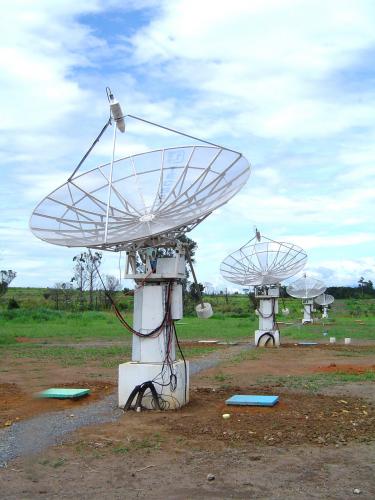
The Instituto Nacional Pesquisas Espacias (INPE), Brazil is building a decimetre radio telescope for observations of the Sun and various galactic, extra-galactic radio sources. In its initial configuration, the BDA had 5 parabolic dish antennas of 4 m diameter each, set up as a one-dimensional array in the east-west direction. The frequency of operation is 1.6 GHz. The length of the longest baseline in the array is 216 m. The temporal and spatial resolution are ~100 msec and ~1.5 arc min respectively. The array is located at Cachoeira Paulista (Latitude:22.69° S; Longitude:45.01° W). The members of the solar radio astronomy group at IIA have contributed to the array configuration, software for data calibration and image synthesis. They have also designed and constructed the digital back end receiver for the telescope.
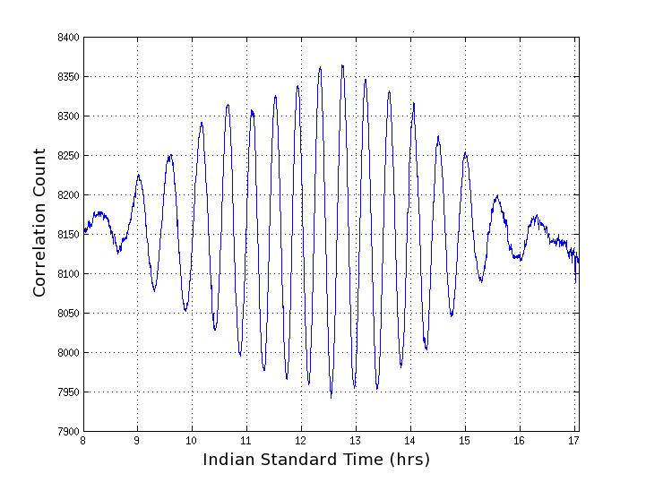
As a part of its public outreach programme, the institute offers a two element radio interferometer operating at 191.4 MHz to science / engineering students pursuing their Bachelor's / Master's degree in colleges / universities. The motive is to help the students learn the basics of radio astronomy through hands-on experience. Interested students may apply for the kit through the Head of their Institution to : The Director, Indian Institute of Astrophysics, Bangalore 560 034. The recipients of the kit will be trained in the observatory to: (i) design, fabricate, and characterize the antenna and receiver system; (ii) develop software for data acquisition and analysis; and (iii) carry out observations of radio emission from the Sun and other strong cosmic radio sources.
The basic receiving system consists of a pair of dipole antennas tuned to receive radio frequency (RF) signal at ~191 MHz. The RF signal incident on each antenna is amplified independently in a broad band amplifier, and then transmitted to the receiver room via coaxial cables. In the receiver room, the signal from each antenna is first passed through a band pass filter having center frequency ~191.4 MHz and half-power bandwidth ~6 MHz, to minimize the contribution from interfering signals at other frequencies. The filtered signal is then mixed with a local oscillator (LO) signal at 180.7 MHz to down convert the RF signal to an intermediate frequency (IF) signal at 10.7 MHz. The output of the mixer is amplified and passed through a band pass filter with center frequency ~10.7 MHz and half-power bandwidth ~1 MHz. The output from the IF filter corresponding to each antenna is then fed to the digital receiver for digitization and correlation. There is also provision for integrating the correlated data before transmission to the computer for storage, display, and analysis.

Recipients of the kit till date:
1. Mohanlal Sukhadia (MLS) University, Udaipur
2. Rajasthan Technical University, Udaipur
3. St.Xavier's College, Kolkata
4. J.C. Bose Institute, Kolkata
5. Indian Institute of Science Education & Research (IISER), Pune
6. Electronics Science Department (Pune University), Pune
7. Indian Centre for Space Physics, Kolkata
 |
- Work is going on at present to increase the spatial resolution and sensitivity of the GRAPH to probe the solar corona with
finer details.
Latitude: 13° 36' 12" North
Longitude : 77° 26' 07" East
Local Time: Indian Standard Time (IST) : IST = GMT + 05 30hrs
Radio Astronomy Field Station
Indian Institute of Astrophysics
Hossur post, Gauribidanur Taluk
Chikkaballapur District - 561210, INDIA
Tel : 91 8155-291655
E-Mail : webmaster[At]iiap.res.in
-
Rail Connection
-
Road Connection
The nearest railway station to the Observatory is Gauribidanur (100km from Bangalore). Trains bound for Dharmavaram, Hindupur and Mumbai stop at Gauribidanur.
By road one can reach the Observatory which is situated near a village called Kotaladinne which is about 8 km from Gauribidanur. The Observatory is well-connected by road from Bangalore via Yelahanka, Doddaballapur.
Click on the image to open Google map