Detectors
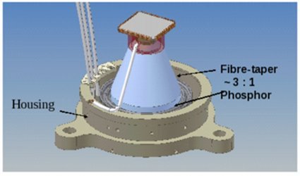
All the three detectors are intensified CMOS type with an aperture of ~40 mm diameter. Construction of the three detectors and their electronics are identical except for the photo-cathodes and the window. A 5 mm thick MgF2 window is used for the FUV detector, while 5 mm thick silica windows are used for the NUV and the VIS detectors. A sketch of the detector module is shown below.

UVIT Detector Module
At the bottom, and hidden by the housing, are the 5 mm thick window with photo-cathode deposited on it, and a set of two micro-channels-plates. The electrons are accelerated by ~ 5 kV and strike the phosphor to emit a pulse of photons. The light from phosphor is transmitted to Star-250 (C-MOS Imager) by a fibre-taper. The fibre-taper also matches the 40 mm diameter of the window to size of the C-MOS Imager (512 X 512 pixels of 25 X 25 microns each).
The gap between photo-cathode and micro-channel-plates is kept small (~ 0.1 mm ) to minimize drift of the photo-electrons. With such small gaps, contribution of the detectors to the PSF is no more than ~ 1" FWHM.
Either the entire array of 512 X 512 pixels can be read, at a max. rate of ~29 frames/s, to capture the full field, or a part of the field can be read in "window" mode at rates up to 200 frames/s, depending on area of the window.
Photon Counting and Integration Modes
The detectors can operate in two distinct modes:
- Photon Counting Mode
- Integration Mode
In the photon counting mode a very high multiplication is obtained in the MCPs such that each photo-electron generated in the short exposure (< 100 ms) is detected as a light pulse in the CMOS imager, and its centroid is found. Thus, for each frame of exposure a list of centroid-positions is obtained from the detector. Information about these positions are transmitted from the spacecraft.
In the integration mode multiplication of the MCP is kept low, and signals in all the pixels of the CMOS detector are obtained. In this mode, many (weak) pulses of light, from many photo-electrons, could fall at the same location; the signal at any location is a measure of how many photo-electrons were detected. Raw frames from CMOS detectors are transmitted.
Photon counting mode gives a much better spatial resolution (< 1.8" FWHM)as compared to the integration mode (~ 5" FWHM) . However, if in a single exposure two or more photon events occur within a separation less than ~ 3 pixels of the CMOS imager (< 10"), these are detected as a single event or rejected as unacceptable event. For imaging full field, minimum exposure time is ~ 34 ms. Therefore, given the background levels, imaging in the VIS channel is normally done in integration mode.
Quantum Efficiencies
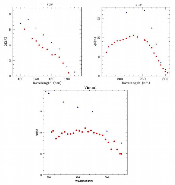
Quantum efficiencies of the detectors have been measured in photon counting mode, with
reference to a NIST calibrated photodiode. These are displayed below:

QE of UVIT Detectors: Values for Ph. Counting mode are shown as red circles. The blue diamonds are for the photocathodes measured by the vendor.